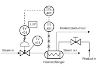
Intended to provide a “picture” of all of piping including the physical branches, valves, equipment, instrumentation and interlocks. The P&ID uses a set of standard symbols representing each component of the system such as instruments, piping, motors, pumps, etc.
P&ID’s can be very detailed and are generally the primary source from where instrument and equipment lists are generated and are very handy reference for maintenance and upgrades. P&ID’s also play an important early role in safety planning through a better understanding of the operability and relationships of all components in the system.
For more information on any process system design or process engineering requirement, visit http://www.processsytemsdesign.com or call (410) 861-6437.
