Showing posts with label process control. Show all posts

Thursday, November 30, 2017

Improving Fan System Performance: A Sourcebook for Industry

Fan System Performance
Typical Fan System
Fans are widely used in industrial and commercial applications. From shop ventilation to material handling to boiler applications, fans are critical for process support and human health.

In manufacturing, fan reliability is critical to plant operation. For example, where fans serve material handling applications, fan failure will immediately create a process stoppage. In industrial ventilation applications, fan failure will often force a process to be shut down (although there is often enough time to bring the process to an orderly stoppage). Even in heating and cooling applications, fan operation is essential to maintain a productive work environment. Fan failure leads to conditions in which worker productivity and product quality declines. This is especially true for some production applications in which air cleanliness is critical to minimizing production defects (for example, plastics injection molding and electronic component manufacturing).

The document below, developed by the US DOE and the Air Movement and Control Association International provides wide ranging information about fans used in industry. You can also download your own full copy of this document from here.

Wednesday, November 8, 2017

Biomass for Power and Heat Generation

There are many potential advantages to using biomass instead of fossil fuels for meeting energy needs. Specific benefits depend upon the intended use and fuel source, but often include: greenhouse gas and other air pollutant reductions, energy cost savings, local economic development, waste reduction, and the security of a domestic fuel supply. In addition, biomass is more flexible (e.g., can generate both power and heat) and reliable (as a non-intermittent resource) as an energy option than many other sources of renewable energy.

Biomass fuels are typically used most efficiently and beneficially when generating both power and heat through CHP (combined heat and power). CHP, also known as cogeneration, is the simultaneous production of electricity and heat from a single fuel source, such as biomass/biogas, natural gas, coal, or oil. CHP provides:
  • Distributed generation of electrical and/or mechanical power.
  • Waste-heat recovery for heating, cooling, or process applications.
  • Seamless system integration for a variety of technologies, thermal applications, and fuel types into existing building infrastructure.
CHP is not a single technology, but an integrated energy system that can be modified depending on the needs of the energy end user. The hallmark of all well-designed CHP systems is an increase in the efficiency of fuel use. By using waste heat recovery technology to capture a significant proportion of heat created as a byproduct in electricity generation, CHP systems typically achieve total system efficiencies of 60 to 80 percent for producing electricity and thermal energy. These efficiency gains improve the economics of using biomass fuels, as well as produce other environmental benefits. More than 60 percent of current biomass-powered electricity generation in the United States is in the form of CHP.

The industrial sector currently produces both steam or hot water and electricity from biomass in CHP facilities in the paper, chemical, wood products, and food-processing industries. These industries are major users of biomass fuels; utilizing the heat and steam in their processes can improve energy efficiency by more than 35 percent. The biggest industrial user of bioenergy is the forest products industry, which consumes 85 percent of all wood waste used for energy in the United States. Manufacturing plants that utilize forest products can typically generate more than half of their own energy from woody waste products and other renewable sources of fuel (e.g., wood chips, black liquor).

Most of the electricity, heat, and steam produced by industrial facilities are consumed on site; however, some manufacturers that produce more electricity than they need on site sell excess power to the grid. Wider use of biomass resources will directly benefit many companies that generate more residues (e.g., wood or processing wastes) than they can use internally. New markets for these excess materials may support business expansion as the residues are purchased for energy generation purposes or new profit centers of renewable energy production may diversify and support the core business of these companies.

Biomass Feedstocks

The success of any biomass-fueled CHP project is heavily dependent on the availability of a suitable biomass feedstock. Biomass feedstocks are widely available in both rural and urban settings and can include:

Rural Resources:
  • Forest residues and wood wastes
  • Crop residues Energy crops Manure biogas
Urban Resources:
  • Urban wood waste
  • Wastewater treatment biogas
  • Municipal solid waste (MSW) and landfill gas (LFG)
  • Food processing residue
Feedstocks vary widely in their sources and fuel characteristics and therefore vary in typical considerations for their utilization. Various biomass resources can require different approaches to collection, storage, and transportation, as well as different considerations regarding the conversion process and power generation technology that they would most effectively fuel.

Process Systems & Design welcomes your inquiries in to biomass processing. With years of engineering experience in this field, PS&D is an outstanding engineering partner for any biomass-to-energy conversion process.

Contact Process Systems & Design by visiting http://www.processsystemsdesign.com or call (410) 861-6437.

Monday, October 9, 2017

Gypsum Processing for Cement, Plaster and Wallboard

Gypsum

Gypsum is calcium sulfate dihydrate (CaSO4 2H2O), a white or gray naturally occurring mineral, and is used as a commercial and generic term for all calcium sulfate materials. Raw gypsum ore is processed into a variety of products such as a portland cement additive, soil conditioner, industrial and building plasters, and gypsum wallboard.

Gypsum ore, from quarries and underground mines, is crushed and stockpiled near a plant. As needed, the stockpiled ore is further crushed and screened to about 50 millimeters (2 inches) in diameter. If the moisture content of the mined ore is greater than about 0.5 weight percent, the ore must be dried in a rotary dryer or a heated roller mill. Ore dried in a rotary dryer is conveyed to a roller mill, where it is ground to the extent that 90 percent of it is less than 149 micrometers (100 mesh). The ground gypsum exits the mill in a gas stream and is collected in a product cyclone. Ore is sometimes dried in the roller mill by heating the gas stream so that drying and grinding are accomplished simultaneously and no rotary dryer is needed. The finely ground gypsum ore is known as landplaster, which may be used as a soil conditioner.

In most plants, landplaster is fed to kettle calciners or flash calciners, where it is heated to remove three-quarters of the chemically bound water to form stucco (CaSO4 1⁄2H2O). Calcination occurs at approximately 120° to 150°C (250° to 300°F) and 0.908 megagrams (Mg) (1 ton) of gypsum calcines to about 0.77 Mg (0.85 ton) of stucco.

In kettle calciners, the gypsum is indirectly heated by hot combustion gas passed through flues in the kettle, and the stucco product is discharged into a "hot pit" located below the kettle. Kettle calciners may be operated in either batch or continuous mode. In flash calciners, the gypsum is directly contacted with hot gases, and the stucco product is collected at the bottom of the calciner.

At some gypsum plants, drying, grinding, and calcining are performed in heated impact mills. In these mills hot gas contacts gypsum as it is ground. The gas dries and calcines the ore and then conveys the stucco to a product cyclone for collection. The use of heated impact mills eliminates the need for rotary dryers, calciners, and roller mills.

Gypsum and stucco are usually transferred from one process to another by means of screw conveyors or bucket elevators. Storage bins or silos are normally located downstream of roller mills and calciners but may also be used elsewhere.

In the manufacture of plasters, stucco is ground further in a tube or ball mill and then batch-mixed with retarders and stabilizers to produce plasters with specific setting rates. The thoroughly mixed plaster is fed continuously from intermediate storage bins to a bagging operation.

In the manufacture of wallboard, stucco from storage is first mixed with dry additives such as perlite, starch, fiberglass, or vermiculite. This dry mix is combined with water, soap foam, accelerators, and shredded paper or pulpwood in a pin mixer at the head of a board forming line. The slurry is then spread between two paper sheets that serve as a mold. The edges of the paper are scored, and sometimes chamfered, to allow precise folding of the paper to form the edges of the board. As the wet board travels the length of a conveying line, the calcium sulfate hemihydrate combines with the water in the slurry to form solid calcium sulfate dihydrate, or gypsum, resulting in rigid board. The board is rough-cut to length, and it enters a multideck kiln dryer, where it is dried by direct contact with hot combustion gases or by indirect steam heating. The dried board is conveyed to the board end sawing area and is trimmed and bundled for shipment.

Wednesday, July 12, 2017

The Ethanol Production Process

Ethanol Plant
Ethanol Plant
Though new technology may eventually blur the distinction between them, ethanol is produced by one of two processes: wet milling and dry milling. Wet mills are more expensive to build, are more versatile in terms of the products they can produce, yield slightly less ethanol per bushel, and have more valuable co-products. Wet milling initially accounted for most of the ethanol fuel production in the United States, but new construction has shifted to dry mills, partly because dry mills cost less to build.

Dry-milling plants have higher yields of ethanol. The wet mill is more versatile, though, because the starch stream, being nearly pure, can be converted into other products (for instance, high-fructose corn syrup (HFCS)). Co-product output from the wet mill is also more valuable.

In each process, the corn is cleaned before it enters the mill. In the dry mill, the milling step consists of grinding the corn and adding water to form the mash. In the wet mill, milling and processing are more elaborate because the grain must be separated into its components. First, the corn is steeped in a solution of water and sulfur dioxide (SO2) to loosen the germ and hull fiber. This 30- to 40-hour extra soaking step requires additional tanks that contribute to the higher construction costs. Then the germ is removed from the kernel, and corn oil is extracted from the germ. The remaining germ meal is added to the hulls and fiber to form the corn gluten feed (CGF) stream. Gluten, a high-protein portion of the kernel, is also separated and becomes corn gluten meal (CGM), a high-value, high-protein (60 percent) animal feed. The corn oil, CGF, CGM, and other products that result from the production of ethanol are termed co-products.

Unlike in dry milling, where the entire mash is fermented, in wet milling only the starch is fermented. The starch is then cooked, or liquefied, and an enzyme added to hydrolyze, or segment, the long starch chains. In dry milling, the mash, which still contains all the feed co-products, is cooked and an enzyme added. In both systems a second enzyme is added to turn the starch into a simple sugar, glucose, in a process called saccharification. Saccharification in a wet mill may take up to 48 hours, though it usually requires less time, depending on the amount of enzyme used. In modern dry mills, saccharification has been combined with the fermentation step in a process called simultaneous saccharification and fermentation (SSF).

Glucose is then fermented into ethanol by yeast (the SSF step in most dry- milling facilities). The mash must be cooled to at least 95deg. F before the yeast is added. The yeast converts the glucose into ethanol, carbon dioxide (CO2), and small quantities of other organic compounds during the fermentation process. The yeast, which produces almost as much CO2 as ethanol, ceases fermenting when the concentration of alcohol is between 12 and 18 percent by volume, with the average being about 15 percent. An energy-consuming process, the distillation step, is required to separate the ethanol from the alcohol-water solution. This two-part step consists of primary distillation and dehydration. Primary distillation yields ethanol that is up to 95-percent free of water. Dehydration brings the concentration of ethanol up to 99 percent. Finally, gasoline is added to the ethanol in a step called “denaturing,” making it unfit for human consumption when it leaves the plant.

The co-products from wet milling are corn oil and the animal feeds corn gluten feed (CGF) and corn gluten meal (CGM). Dry milling production leaves, in addition to ethanol, distiller’s dried grains with solubles (DDGS). The feed co-products must be concentrated in large evaporators and then dried. The CO2 may or may not be captured and sold.

Reprinted from USDA publication “New Technologies in Ethanol Production”

Thursday, June 1, 2017

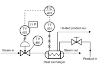
Piping & Instrumentation Diagram in Process Control

Process and Control Flow Diagrams
P&ID's (piping & instrumentation diagrams), or Process and Control Flow Diagrams, are schematic representations of a process control system and used to illustrate the piping system, process flow, installed equipment, and process instrumentation and functional relationships therein.

Intended to provide a “picture” of all of piping including the physical branches, valves, equipment, instrumentation and interlocks. The P&ID uses a set of standard symbols representing each component of the system such as instruments, piping, motors, pumps, etc.

P&ID’s can be very detailed and are generally the primary source from where instrument and equipment lists are generated and are very handy reference for maintenance and upgrades. P&ID’s also play an important early role in safety planning through a better understanding of the operability and relationships of all components in the system.


For more information on any process system design or process engineering requirement, visit http://www.processsytemsdesign.com or call (410) 861-6437.

Monday, May 22, 2017

Safety Video: Refinery Plant Explosion Animation

Brought to you as a courtesy of U.S. Chemical Safety and Hazard Investigation Board (CSB.gov) and Process Systems and Design (http://www.processsystemsdesign.com).

Video reviews the circumstances that led up to a 2015 explosion at a refinery in Torrence CA.


Process Systems and Design is a team of technical and business experts across a spectrum of industries who specialize in all aspects of process control and material handling equipment design, construction, and support. They can be reached by visiting http://www.processsystemsdesign.com or calling (410) 861-6437.