Showing posts with label Engineering. Show all posts

Tuesday, December 19, 2017

Pultruded FRP Composites as an Alternate to Steel

Pultruded FRP suspendible roof structure
Pultruded FRP suspendible roof structure.
Pultrusion is a term that describes a manufacturing process for producing continuous lengths of FRP (fiberglass reinforced plastic) where reinforcing fibers are saturated with resin and pulled through a heated die to form a part. The result is a straight, constant cross-section profiles similar to standard steel shapes.

Pultruded composite sections can be used to design and install lightweight, corrosion-resistant and electrically non-conductive alternatives to steel structures, particularly where speed and ease of construction are important. Pultruded FRP has performance characteristics similar to other construction metals, but unlike steel, it is EM/RF transparent and doesn’t disrupt equipment signals.

Benefits:
  • Pound-for-pound stronger than steel.
  • Comparable structural performance to other metals such as aluminum, but without the conductivity, corrosion or impact limitations. 
  • Can be painted, coated or pigmented during manufacture for little-to-no maintenance in highly aggressive environments
  • Designed for UV performance
  • Enables rapid cleaning with aggressive solvents at high pressures
  • Meets industry requirements for durability, smoothness, absorbency, color, corrosion resistance and washability
Typical Uses:
  • Structural profiles and plates
  • Decking and planking
  • Platforms, stairs, ladders and cages
  • Handrails, guarding and kickplates
  • Grating and gridmesh
  • Bridge components
  • Structural building panels
  • Sheet piling and round pile
  • Containment systems
  • Ballistic and storm panels
  • Connection hardware
Pultruded FRP composites are ideal for structural elements where a strong, lightweight material is needed; corrosion is a concern for steel or other metals; RF permeability is needed; and low thermal or electrical conductivity is important.

To discuss using pultruded FRP composites on your next project, contact Process Systems Design by calling (410) 861-6437 or visit https://www.processsystemsdesign.com.
Sunday, December 10, 2017

Consider the Possibility of Constituent By-products in Your Process Heating System

Process Heating System
It is estimated that over 7,000 TBtu/year (Trillion British Thermal Units) of energy is used for process heating by the manufacturing sector in the United States. This energy is in the form of fuels—mostly natural gas with some coal or other fuels—and steam generated using fuels such as natural gas, coal, by-product fuels, and some others.

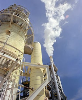
Combustion of these fuels results in the release of heat, which is used for process heating, and in the generation of combustion products that are discharged from the heating system. All major US industries use heating equipment such as furnaces, ovens, heaters, kilns, and dryers. The hot exhaust gases from this equipment, after providing the necessary process heat, are discharged into the atmosphere through stacks.  The temperature of the exhaust gases discharged into the atmosphere from heating equipment depends on the process temperature and whether a waste heat recovery (WHR) system is used to reduce the exhaust gas temperature. The temperature of discharged gases varies from as low as 200°F to as high as 3000°F.

Combustion products themselves, generated from well-designed and well-operated burners using gaseous and light liquid fuels, are relatively clean and do not contain particles or condensable components that may require “cleanup” before discharge into the atmosphere. However, during the heating process, the combustion products may react or mix with the product being heated and may pick up constituents such as reactive gases, liquid vapors, volatiles from low-melting-temperature solid materials, particulates, condensable materials, and the like.

Some or all of these constituents, particularly at high temperatures, may react with materials used in the construction of downstream heat WHR equipment and create significant problems.

Potential Problems:
  • Chemical reaction of exhaust gases and their solid or vapor content with the materials used in the WHR equipment.
  • Deposit of particulates in or on surfaces of WHR equipment.
  • Condensation of organics such as tars and inorganic vapors such as zinc oxides and boron on heat exchanger surfaces.
  • Erosion of heat exchanger components by the solids in the exhaust gases. 
Many of these problems are compounded by the high temperature of the exhaust gases, uneven flow patterns of the hot gases inside the heat exchanger, and operating variations such as frequent heating and cooling of the heat exchanger.

Dealing with industrial heating processes in which the exhaust gases are at high temperatures, or that contain all reactive constituents, or can be considered as harsh or contaminated are important considerations for the process engineer.  If unsure, professional advice from knowledgeable consultants should be sought to optimize the heating system. To discuss any process heating requirement you may have, contact Process Systems & Design at https://www.processsystemsdesign.com or by calling (410) 861-6437.

Wednesday, October 18, 2017

A Leading Authority on E-Liquid Manufacturing Equipment

As an alternative to smoking tobacco, inhaling vaporized liquids containing nicotine, flavors and vegetable glycerin has become very popular. The name this new industry has been given is “Vaping” and the products used in electronic vaporizers is referred to as E-Liquid. E-Liquids are heated to vapor, then inhaled, and the various compounds (such as nicotine) are adsorbed by the mouth, nose and lungs.

Because of the obvious health concerns of inhaling flavor compounds, stabilizers, and other E-Liquid constituents,  FDA (Food and Drug Administration) oversight is acute. Considering this, the E-Liquid industry must be prepared to implement strict cGMP manufacturing processes that include all aspects of production - from storage and blending, flow of ingredients, and finished product - with strict FDA record-keeping compliance.

Since the E-Liquid/Vaping industry is relatively new, companies considering a move into producing and selling E-Liquids are finding it difficult to find experienced, qualified equipment designers and consultants. Not only are their few qualified vendors, but the legislative constraints on the industry seem to change frequently. The right equipment partner needs to not only have the technical know-how to build safe, reliable, and efficient equipment, but they also must be on top of FDA and other governmental factors.

Process Systems & Design, located in Westminster, MD is one of the world’s leading experts in E-Liquid manufacturing. PS&D developed the first FDA compliant, safe, accurate, automated, and self-contained e-Liquid compounding system for the e-liquid/vaping industry.  You can lean more about Process Systems & Design at http://www.processsystemsdesign.com/e-liquid or by calling (410) 861-6437.

Thursday, September 28, 2017

The VIPER Automated, FDA Compliant, Self-contained e-Liquid Compounding System

PS&D's Viper is the first FDA compliant, safe, accurate, automated, and self-contained e-Liquid compounding system for the e-liquid vaping industry.

The production system is integrated with a flexible batch management system that provides a platform for automatic control and electronic record-keeping to comply with FDA regulations 21 CFR 210, 211, and 11. Proven products from Rockwell Automation provides the core of control and information management system. It provides the authorized operator with a secure tool for designing flexible recipes that combine operator-entered and automatic data collection into a single work flow. In-process weights are collected automatically and used to manage the flow of ingredients and finished products between storage and blending vessels. System components, including motors and automatic valves are sequenced according to the recipes’ logic. Data are stored in a relational database management system for long-term storage and reporting. PS&D supports the information technologies associated with the recipe management and data collection processes through secure cloud-based computing and network communications platforms.

For more information, visit http://www.processsystemsdesign.com/e-liquid or call (410) 861-6437.

Tuesday, September 12, 2017

From Biomass to Biofuel

Biomass converted to gasoline
Biomass converted to gasoline (image courtesy of epa.gov)
Biomass resources run the gamut from corn kernels to corn stalks, from soybean and canola oils to animal fats, from prairie grasses to hardwoods, and even include algae.

In the long run, we will need diverse technologies to make use of these different energy sources. Some technologies are already developed; others will be. Today, the most common technologies involve biochemical, chemical, and thermochemical conversion processes.


Ethanol, today’s largest volume biofuel, is produced through a biochemical conversion process. In this process, yeasts ferment sugar from starch and sugar crops into ethanol. Most of today’s ethanol is produced from cornstarch or sugarcane. But biochemical conversion techniques can also make use of more abundant “cellulosic” biomass sources such as grasses, trees, and agricultural residues.

Researchers develop processes that use heat, pressure, chemicals, and enzymes to unlock the sugars in cellulosic biomass. The sugars are then fermented to ethanol, typically by using genetically engineered micro- organisms. Cellulosic ethanol is the leading candidate for replacing a large portion of U.S. petroleum use.

A much simpler chemical process is used to produce biodiesel. Today’s biodiesel facilities start with vegetable oils, seed oils, or animal fats and react them with methanol or ethanol in the presence of a catalyst. In addition, genetic engineering work has produced algae with a high lipid content that can be used as another source of biodiesel.

Algae are a form of biomass which could substantially increase our nation’s ability to produce domestic biofuels. Algae and plants can serve as a natural source of oil, which conventional petroleum refineries can convert into jet fuel or diesel fuel—a product known as “green diesel.”

Researchers also explore and develop thermochemical processes for converting biomass to liquid fuels. One such process is pyrolysis, which decomposes biomass by heating it in the absence of air. This produces an oil-like liquid that can be burned like fuel oil or re ned into chemicals and fuels, such as “green gasoline.” Thermochemical processes can also be used to pretreat biomass for conversion to biofuels.

Another thermochemical process is gasification. In this process, heat and a limited amount of oxygen are used to convert biomass into a hot synthesis gas. This “syngas” can be combusted and used to produce electricity in a gas turbine or converted to hydrocarbons, alcohols, ethers, or chemical products. In this process, biomass gasifiers can work side by side with fossil fuel gasifiers for greater flexibility and lower net greenhouse gas emissions.

In the future, biomass-derived components such as carbohydrates, lignins, and triglycerides might also be converted to hydrocarbon fuels. Such fuels can be used in heavy-duty vehicles, jet engines, and other applications that need fuels with higher energy densities than those of ethanol or biodiesel.

Sunday, September 10, 2017

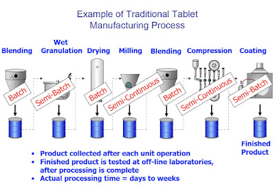
Batch Processing vs. Continuous Manufacturing in Pharmaceuticals

Not much has changed in pharmaceutical manufacturing over the last 50 years. While technological advancements in creating new drugs have been made, the pharmaceutical industry still relies heavenly on traditional step-by-step batch processing.

Alternatively, continuous manufacturing, which is the preferred manufacturing process in automotive, food & beverage, and refining industries – has been slow to gain acceptance in pharmaceutical production, largely because of high startup costs.


Batch Processing vs. Continuous Manufacturing

Comparisons


Batch Manufacturing:

All materials are charged before the start of processing and discharged at the end of
processing.

  • Examples: Bin blending, lyophilization, some reactions

Continuous Manufacturing

Material is simultaneously charged and discharged from the process

  • Examples: Petroleum refining, much of food processing

VARIATIONS


Semi-Batch (Fed-batch)Manufacturing

Materials are added during processing and discharged at the end of processing.

  • Examples: Wet granulation, fermentation

Semi-Continuous Manufacturing

Like continuous manufacturing, but for a discrete time period.

  • Examples: Roller compaction, tablet compression

Batch Processing


Although reliable, batch processing is viewed a slower manufacturing method for pharmaceuticals, and also less safe because of higher risk for contamination and errors between steps. Pharmaceutical manufacturers have no choice but to continually evaluate and implement the best possible production processes. Considering an estimated $50 billion per year is wasted on on inefficient processes in the pharmaceutical industry, it makes great sense to migrate toward continuous manufacturing.

Continuous Manufacturing

Continuous manufacturing is faster, more efficient, and inherently safer. Improved safety is derived from rigid quality control requirements in continuous manufacturing. Considering this, the concern over large plant and equipment outlays looses is impact. Many experts maintain that continuous manufacturing is ultimately a far less costly production process (considering efficiency and safety), once the initial plant, equipment, and training costs are amortized.


Thursday, June 1, 2017

Piping & Instrumentation Diagram in Process Control

Process and Control Flow Diagrams
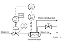
P&ID's (piping & instrumentation diagrams), or Process and Control Flow Diagrams, are schematic representations of a process control system and used to illustrate the piping system, process flow, installed equipment, and process instrumentation and functional relationships therein.

Intended to provide a “picture” of all of piping including the physical branches, valves, equipment, instrumentation and interlocks. The P&ID uses a set of standard symbols representing each component of the system such as instruments, piping, motors, pumps, etc.

P&ID’s can be very detailed and are generally the primary source from where instrument and equipment lists are generated and are very handy reference for maintenance and upgrades. P&ID’s also play an important early role in safety planning through a better understanding of the operability and relationships of all components in the system.


For more information on any process system design or process engineering requirement, visit http://www.processsytemsdesign.com or call (410) 861-6437.

Monday, May 22, 2017

Safety Video: Refinery Plant Explosion Animation

Brought to you as a courtesy of U.S. Chemical Safety and Hazard Investigation Board (CSB.gov) and Process Systems and Design (http://www.processsystemsdesign.com).

Video reviews the circumstances that led up to a 2015 explosion at a refinery in Torrence CA.


Process Systems and Design is a team of technical and business experts across a spectrum of industries who specialize in all aspects of process control and material handling equipment design, construction, and support. They can be reached by visiting http://www.processsystemsdesign.com or calling (410) 861-6437.